Free Field Reporting template
Geotechnical Shaft Mapping Engineering Report Template
No credit card required.
Need a safety and quality check for your shafts and caissons? Sitemate's Geotechnical Shaft Mapping Engineering Report already contains all the fields needed to create a complete and compliant report. The template is also designed with a user-friendly interface that helps you complete the report with just a few taps and clicks.
This Geotechnical Shaft Mapping Engineering Report can easily be modified to match your workflow. By using Sitemate's Dashpivot platform, an AI assistant will help you create a report that works with your internal processes. Additionally, the AI assistant can help you complete the report and streamline the reporting process.
- 100% fully editable Geotechnical Shaft Mapping Engineering Report
- Export your Geotechnical Shaft Mapping Engineering Report to PDF or CSV
- Access your Geotechnical Shaft Mapping Engineering Report on mobile, tablet or computer
- Thousands of templates including other Field Reporting templates
 Click to preview
Trusted by thousands of companies, projects & teams worldwide


See how this Geotechnical Shaft Mapping Engineering Report compares to traditional Word, Excel, and PDF-based processes
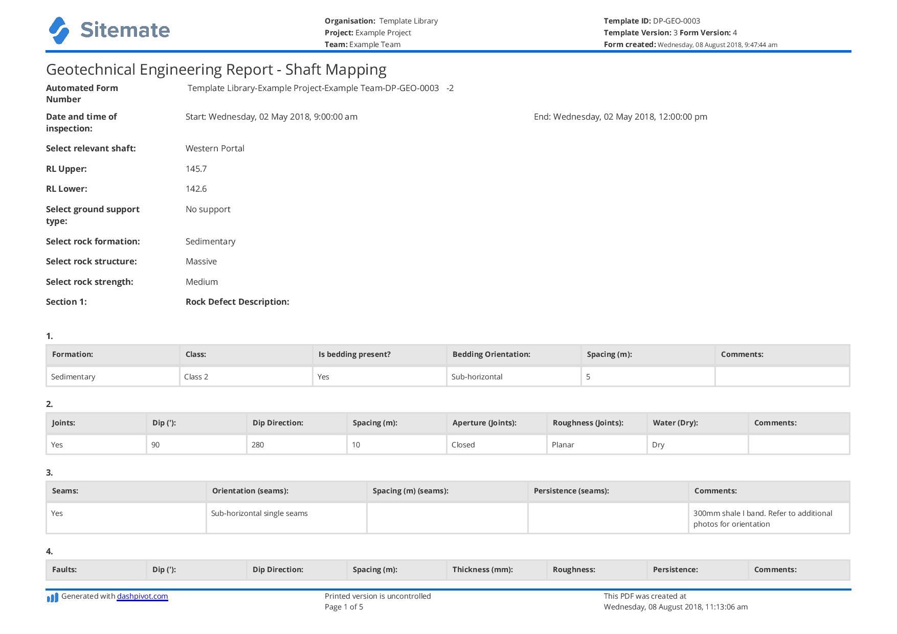
Curious how this Geotechnical Shaft Mapping Engineering Report works? Check out the example below to see exactly what comes pre-structured from general project information and shaft location data through to rock mass classification tables, discontinuity logs, groundwater observations, and engineer sign-off sections. You can generate your version just as quickly, export it as a custom form with your company's branding and project details, and have a ready-to-use Geotechnical Shaft Mapping Engineering Report in your hands within minutes

This Geotechnical Shaft Mapping Engineering Report Sample Was Generated With Dashpivot
This Geotechnical Shaft Mapping Engineering Report template was built using Dashpivot's field reporting platform, which allows geotechnical engineers and project teams to create structured digital field reports with repeatable log tables, photo attachments, dropdown classification fields, e-signatures, and PDF export — all accessible from a mobile device in the field or a desktop in the office.
- Access, edit and complete your Geotechnical Shaft Mapping Engineering Report from any device - mobile, tablet or computer.
- Print, download or send your Geotechnical Shaft Mapping Engineering Report as perfectly formatted PDF documents with your company logo.
- Store your Geotechnical Shaft Mapping Engineering Report securely online, where they can be searched and found in seconds
- Invite internal and external parties to see, edit and sign off on Geotechnical Shaft Mapping Engineering Report online.
Need a version for your own site?
Storm, the AI agent in Dashpivot, can build one from a short description or the form you already use.


 GLOBAL


Template guide
Learn More About the Geotechnical Shaft Mapping Engineering Report
What is a Geotechnical Shaft Mapping Engineering Report?
A Geotechnical Shaft Mapping Engineering Report is a structured field and office document used by geotechnical engineers to record, classify, and interpret the subsurface conditions exposed during shaft excavation. It captures real-time observations of rock and soil materials encountered at each shaft lift or bench, including lithology, rock mass classification, discontinuity orientation and condition, groundwater inflows, and any anomalies that differ from the pre-construction geotechnical model. The report typically references findings against the project's geotechnical baseline report (GBR) or geotechnical data report (GDR) to flag deviations that may affect design, constructability, or safety.
Applicable Standards and Policies for Geotechnical Shaft Mapping Engineering Report
Construction projects always need a Geotechnical Shaft Mapping Engineering Report to demonstrate that the shafts are resting on a strong soil layer. Having strong structural integrity in the ground helps engineers establish the best foundation for the building. Additionally, making the report would ensure compliance with the following standards.
- FHWA-NHI-10-016 — Drilled Shafts: Construction Procedures and LRFD Design Methods
- AASHTO LRFD Bridge Design Specifications
- ODOT Geotechnical Design Manual
- WSDOT Geotechnical Design Manual (M 46-03)
- IDOT Geotechnical Manual
- ISRM Suggested Methods for Rock Mass Description
- ASTM D5878 — Standard Guides for Using Rock-Quality Designation (RQD)
- ASTM D2487 — Classification of Soils for Engineering Purposes (USCS)
Staff Members and Parties That Use the Geotechnical Shaft Mapping Engineering Report
Geotechnical Shaft Mapping Engineering Reports are completed by personnel who have sufficient knowledge in subsurface site investigations, earthworks, and retaining structures. It would be best that the following personnel be involved in creating or completing a Geotechnical Shaft Mapping Engineering Report.
- Geotechnical Engineers: These personnel are the primary authors of the report. They have the complete expertise to make a comprehensive report on shaft mapping.
- Structural Engineers: These are the personnel that plan and design the building. They would need the Geotechnical Shaft Mapping Engineering Report as a reference in designing the foundations of the building.
- Project Managers: A project manager ensures that the operation, from designing the building to constructing it, moves smoothly. They plan the schedules and review reports, such as the Geotechnical Shaft Mapping Engineering Report.
Business Risks Reduced by the Geotechnical Shaft Mapping Engineering Report
A Geotechnical Shaft Mapping Engineering Report is not just a paper. It is vital in many aspects of the project, as it serves as a primary reference for important calculations to ensure a building does not collapse. Failing to complete a report would expose the company to the following business risks:
- Poor engineering decisions that affect shaft stability
- Unidentified geotechnical issues that result in costly repairs
- Increase risk of rockfalls and collapse
- Compromised staff safety
- Regulatory compliance issues
- Difficulty with future maintenance
Business Opportunities Created by the Geotechnical Shaft Mapping Engineering Report
Completing a Geotechnical Shaft Mapping Engineering Report really speaks volumes on how companies only want top-quality work. It shows how companies go into the details to refine and build a structure with integrity. Making the report also presents the following business opportunities:
- Project outcomes are stronger
- Competitive advantages
- Commercial advantages
- A more efficient operational process
- Good standing on quality compliance
- Good standing in safety compliance
What makes a good Geotechnical Shaft Mapping Engineering Report?
A good Geotechnical Shaft Mapping Engineering Report should contain the following sections:
- A general information section
- Information on rock defect formation
- Information on rock defect joints
- Information on the seams
- Information on faults in the area
- Information on the shears
- Sketches
- Instruction for ground support
How to Create a Geotechnical Shaft Mapping Engineering Report
Building a complete and compliant Geotechnical Shaft Mapping Engineering Report requires the right structure, the right field data, and a clear process for moving from raw observations to a certified engineering deliverable. The following steps walk through how to create a report from scratch, whether you are building a paper-based template or a digital form.
Prerequisites before making a Geotechnical Shaft Mapping Engineering Report
- Project information and parameters
- Site clearance
- Geotechnical report
- Soil laboratory results
- Mapping tools
- Competent personnel
- Local standards
Add the general information section
This section provides details on which area is being assessed. It should have the following fields:
- Date and time of inspection
- Relevant shaft inspected
- Reduced level upper
- Reduced level lower
- Ground support type
- Rock formation
- Rock structure
- Rock strength
Add the rock defect section
This section details information on the following:
- Formation
- Joints
- Seams
- Faults
- Shear
Add the visual details section
This section allows users to add photos and sketches to support the details in the report. It should have the following fields:
- Photos
- Sketches
Add the instructions for ground support
This provides a guide on the measures needed to fortify the support. It should have the following fields:
- Comments and notes
- Verification of whether strip drains and weeper holes are required.
- Verification of whether additional strip drains and weeper holes are required.
- Verification of whether face mapping is within the expectations of the geological model.
- Geotechnical engineer signature
Geotechnical Shaft Mapping: Identifying Ground Conditions During Excavation
As shaft excavation progresses, workers may encounter different ground conditions, such as fractured rocks, weak soil, groundwater, and unstable areas. These conditions can affect the stability of the shaft and create risks if workers do not properly assess them. A Geotechnical Shaft Mapping Engineering Report helps record the ground conditions observed at different depths of the shaft, including rock types, fractures, groundwater, and other geological features. This provides engineers a better understanding of the ground and helps them identify areas that may need additional support or attention. It also provides a record of the conditions encountered throughout the excavation.
How to Create Your Geotechnical Shaft Mapping Engineering Report in an App or Software System
A well-designed Geotechnical Shaft Mapping Engineering Report transforms a labor-intensive, error-prone paper process into a streamlined field workflow that produces a professional deliverable in a fraction of the time. When field engineers complete the report on a mobile device directly at the shaft, observations are recorded in real time against pre-structured fields, photographs are automatically attached to the relevant depth interval, and required fields are flagged as incomplete before the form can be submitted.
How to make a Geotechnical Shaft Mapping Engineering Report in an app
Using an app that employs digital forms instead of paper-based ones may help improve the process by:
- Assistance with artificial intelligence (AI).
- Having fewer manual data entries.
- All produced forms are stored in a single-access cloud.
- Reformatting is straightforward and can be adapted to new protocols or updated standards.
- Workflows and notifications may be automated and scheduled.
- Improved template design and look.
Creating the information section
- Add a date and time range field for the inspection date and time.
- Add a selection field for the relevant shaft being inspected. Selection items must be areas where the shafts are installed. You can add colors to each selection item to make the report more appealing.
- Add number fields for the upper and lower reduced levels.
- Add a multiple-choice field for the ground support types. Add the following selection items: shotcrete, mesh, bolts, pins/nails, and no support. You can add colors to each selection item to make the report more appealing.
- Add a selection field for the rock formation type. Provide the following selection items: igneous, sedimentary, and metamorphic. You can add colors to each selection item to make the report more appealing.
- Add a selection field for the rock structure type. Provide the following selection items: massive, layered, and fragmented. You can add colors to each selection item to make the report more appealing.
- Add a selection field for the rock strength. Provide the following selection items: weak, medium, high, and self-supporting. You can add colors to each selection item to make the report more appealing.
Creating the rock defect description section
- Add a 6-column table where users can freely add rows for the formation field.
- Add an 8-column table where users can freely add rows for the joints field.
- Add a 5-column table where users can freely add rows for the seams field.
- Add an 8-column table where users can freely add rows for the faults field.
- Add an 8-column table where users can freely add rows for the shear field.
Formatting the formation field table
- Format the first column as a text field for the formation.
- Format the second column as a text field for the class.
- Format the third column as a text field for the presence of beddings.
- Format the fourth column as a text field for the bedding orientation.
- Format the fifth column as a number field for the spacing.
- Format the last column as a text field for the comments.
Formatting the joint field table
- Format the first column as a text field for the joints.
- Format the second column as a number field for the dip.
- Format the third column as a text field for the direction of the dip.
- Format the fourth column as a number field for the spacing.
- Format the fifth column as a text field for the aperture of joints.
- Format the sixth column as a text field for the roughness of joints.
- Format the seventh column as a text field for the amount of water present.
- Format the last column as a text field for the comments.
Formatting the seams field table
- Format the first column as a text field for the seams.
- Format the second column as a text field for the orientation of the seams.
- Format the third column as a number field for the spacing.
- Format the fourth column as a text field for the persistence.
- Format the last column as a text field for the comments.
Formatting the faults and shear fields tables
- Format the first column of each table as a text field for the faults and shears.
- Format the second column of each table as a number field for the dip.
- Format the third column of each table as a text field for the direction of the dip.
- Format the fourth column of each table as a number field for the spacing.
- Format the fifth column of each table as a number field for the thickness.
- Format the sixth column of each table as a text field for the roughness.
- Format the seventh column of each table as a text field for the persistence.
- Format the last column of each table as a text field for the comments.
Creating the visual support section
- Add a photo field where users can upload photos relevant to the findings of the report.
- Add a sketch field where users can make freehand drawings and schematics.
Creating the instructions for the ground support section
- Add a multiple-text field for the additional comments and notes.
- Add a yes-and-no selection field to verify if strip drains or weeper holes are required. Don't forget to leave a space for comments.
- Add a yes-and-no selection field to verify if additional strip drains or weeper holes are required. Don't forget to leave a space for comments.
- Add a yes-and-no selection field to verify if face mapping is within the expectations of the geological model.
- Add a signature field for the Geotechnical engineer completing the report.
Frequently Asked Questions
Who completes the Geotechnical Shaft Mapping Engineering Report?
The report is generally prepared by a qualified geotechnical engineer, engineering geologist, or another competent professional experienced in geological mapping and ground assessment. Other site personnel may assist with recording measurements, photographs, and excavation details.
When should the report be completed?
The report should be completed during shaft excavation, as new sections of the shaft become exposed and can be safely inspected. Mapping should be carried out at the intervals required by the project's geotechnical requirements.
Should groundwater conditions be included in the report?
Yes. Record groundwater seepage, water inflows, wet areas, and other signs of water entering the shaft. Where possible, include the location and estimated severity of the inflow, as these conditions may affect excavation stability and support requirements.
How does shaft mapping help determine ground support requirements?
Shaft mapping provides information about the geological conditions and discontinuities that may affect ground stability. Engineers use these observations alongside design assessments and other investigation results to evaluate whether existing support measures are suitable or need to be reviewed.
About the Author

Felmar Mantalaba
Content Engineer
 LinkedIn
Education
Cebu Institute of Technology - University - Mechanical Engineering with Mechatronics
Bio
Felmar is a mechanical engineer, whose four years of experience in the mining industry inspired him to write and share stories to progress the revolution of new technologies and create smarter, smoother ways of living.
Past Projects
Safety, Health, and Environment Management System (SHEMS) CoordinationSHEMS Coordinator at Atlas Consolidated Mining, ensuring organizational compliance with ISO 14001 and ISO 45001 standards, performing risk assessments, developing policies, and conducting audits and inspections to maintain a safe and environmentally responsible workplace.
Maintenance Management and OptimizationSenior Maintenance Manager (OIC) leading equipment maintenance and operational efficiency initiatives, reducing downtime by 10%, improving Mean Time Between Failure (MTBF) and Mean Time To Repair (MTTR) for major equipment, and managing maintenance schedules, manpower, and materials, while overseeing capital project optimization.
Inspection Engineering and Equipment ReliabilityInspection Engineer responsible for technical blueprint interpretation, vendor collaboration, preventive maintenance scheduling, and data collection for vibration and temperature readings, delivering actionable recommendations and comprehensive reports to improve equipment reliability and operational performance.
End-to-End Operational Oversight in Mining EngineeringContributed to multiple facets of operational management, including SHEMS compliance, maintenance optimization, inspections, and capital project evaluation, integrating safety, reliability, and efficiency improvements across all stages of copper production operations.
Version history
Last edited on 13 November 2026, template version 25-11-v1